Thursday, June 21, 2012

The case of the Yamaha with a Lawnmower switch

A few days ago I answered an ad on Craigs List for
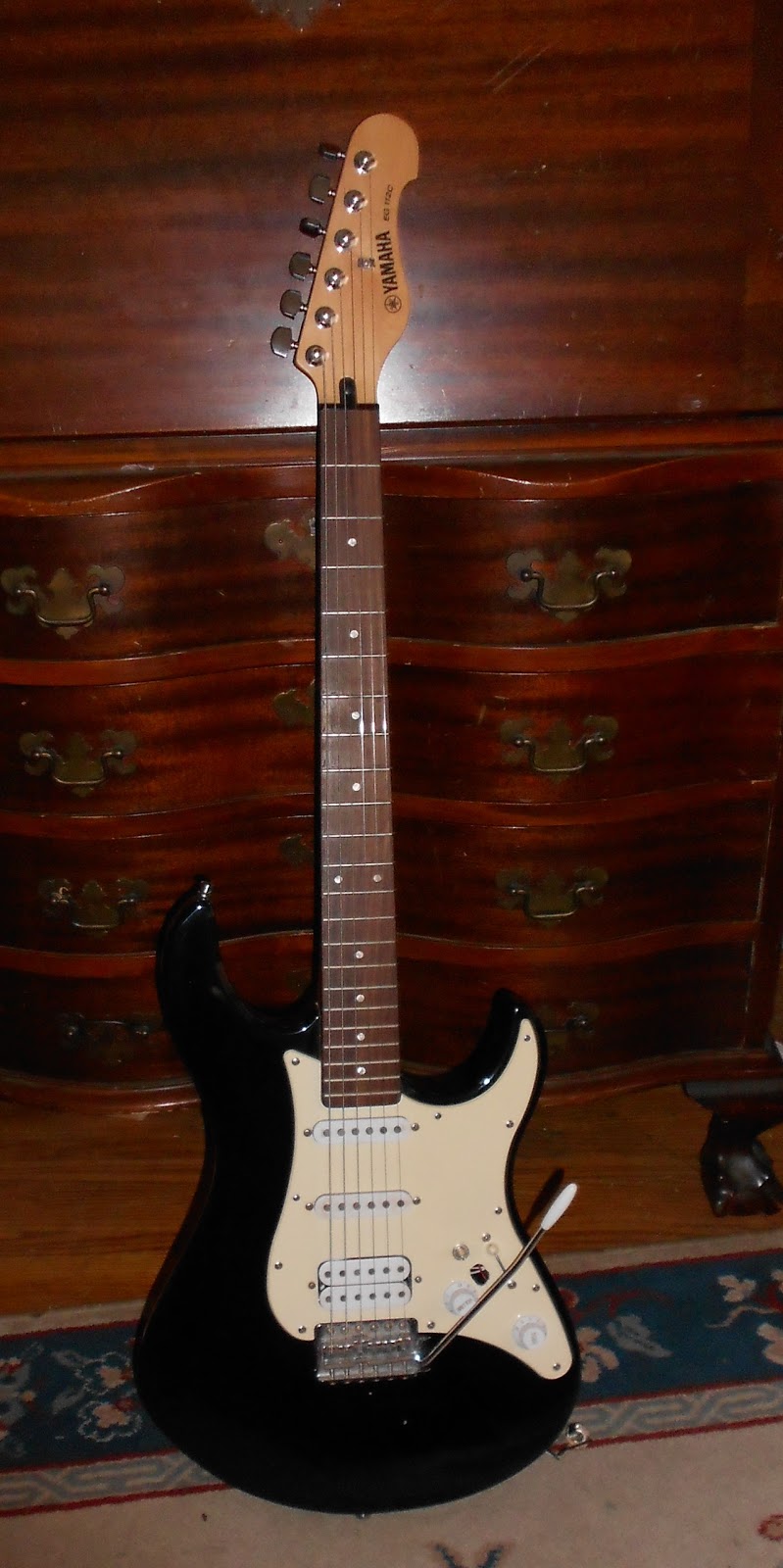
a Yamaha electric guitar for $ 20. The picture looked a bit vague, but I thought for the price, I'd take it.  When I met the guy, I had to hide my laughing inside when I saw how someone tried to repair it.  The blade was missing from the 5 way switch, and they put next to it a switch identical to the one I used for a kill switch on my riding lawn mower!  Next to that, was a small push button switch.  I paid the guy and he said this goes with it.  It came with a nice stand and a bag of cords and a cheap tuner.

I got home and looked closer.  The jack was not in sight, but wads of electric tape, folded and screwed to the lower edge of the guitar.  I didn't even try to diagnose anything, I fired up the soldering iron, cut the wires going to the two bogus switches, and unsoldered the pickup leads and the rest of the wires from the original switch which was in fact still in the guitar.

I then removed all the switches leaving the pickups, volume and tone controls.  The "lawnmower" switch left an ugly irregular hole which is still there for now.  The other added switch, luckily was a small neat round hole. 

The next step was to take Ohm resistance readings on the pickups and pots.  They all seemed to be alive.  I found three used switches in a parts drawer which I could use; a 3 way Tele (or Vintage Strat), an import YM-50 5 way switch, and a new Stew-Mac Super Switch with 4 poles, 5 lugs to a pole.  I did not want to use the Super Switch on this baby.  The used Tele switch would limit my pickup selections so I opted for the used YM-50 switch.

I tinned all the wires and in some cases, cut back and re-tinned.  After wiring up the new switch, it hummed, but the pickups were not working.  I again took readings with the multi meter and it should be working.  I was guess'n the used switch of mine was bad.  There was still one thing I could try with the switch.  I was only using 1/2 of the switch, the other 1/2 would be used to run wires to tone controls.  This model Yamaha, had a single volume and single tone control wired off the volume, not the switch as is the way with a Strat.  I decided to wire the pickups to the other 1/2 of the switch.  Bingo!  Everything worked.  I now had a functional three pickup guitar wired to a 5 way switch.  Now, what could I do bout those two extra holes in the pickguard?  Again, I dove into the parts box and found a mini push-pull pot, and a mini On/On switch.  I decided to use the mini switch to wire the neck pickup to as well as the main 5 way switch.  That gave the guitar two more selections or tone options.  With the original switch, the neck pickup can be selected alone or with the middle pickup.  The remaining 3 positions were to select the middle alone, the middle and bridge, and the bridge alone.  In those remaining 3 positions, I now can add the neck pickup too.  That gives the option of using the neck and bridge together or even all three together. The only part I needed now was a jack plate.  I got a football shaped one for $ 4.50.  I might as well install a new jack too.  After I strung her up, I could see the neck needed a truss rod adjustment.  The vintage tremolo system had been screwed down tight making the bar useless.  I got it adjusted nice and shimmery loose and it stayed in tune pretty good.  As for the ugly hole left by the "lawnmower"switch, maybe I'll put in a doll googly eye!


Wednesday, May 16, 2012

Shadow's Supro's Sick!


While rehearsing with an old band mate from years back, last night, he showed me his Supro Lap Steel and wondered if I could breathe any new life back in her.  The pickup was cutting out on him and worse yet, one of the tuning knobs had broken away, leaving just the steel shaft.  He acquired it years ago for $ 15.00 at a lawn sale.  He did not want to put any big investment in it. 

The body had two huge gashes in it! 

The first thing I did was plug it in and play it.  It seemed to work OK.  The tone control did not seem to work, but the volume rev'd up n down good.

Shadow, having told me that it broke up and was noisy's words rang in my ears as I opened her up.

Someone, years ago had changed the jack.  They replaced it with an enclosed long acoustic guitar jack with the strap button.  It was pressed in tight.  When I got it apart, one of the two wires going to the jack had broke off.  I used my handy dandy knob puller to slowly pull the jack out.  A quick solder to the ole wire and tapped the jack back into the body using a rubber hammer.  Now for a quick clean'n lube to the pots with WD 40.  Using Electronic Contact Cleaner on these old pots could result in freezing them up for good.  The tone control was not working because the old original oil/paper capacitor was Kaput.  I made a judgement call on this relic, worn though she is.  I decided to leave the cap in the system for originality.  Knowing my friend, he may run it through a wah pedal which will alter the tone. 

Now for the broken tuner. 

The tuners were made by Klusin, as many in the 40's and 50's.  I removed the cover, exposing the gear and shafts.  I was hoping that it was the type of tuner where I could bend open the keepers a bit and slide out the broken shaft.  No cigar.  These babies do not come apart.  John did not want to change the tuners if possible.  The buttons on this were smaller than a guitar; more like a mandolin.  I did have  one half of a set of mando tuners on a strip.  I took one tuner off the strip and locking the shaft end in a vise, I cut the button off the shaft using a hack saw.  Next, locking my cut off button, face up in a small vise, I placed on the drill press.  I used a drill close to the shaft size (A Mistake!) to attempt to drill out the steel shaft end out of the button.  I've read where guys use all sorts of elaborate techniques to establish the center of the part to drill, but those expertise's are beyond my skills.  Well, the button tapers down where you place your fingers to hold and turn it.  My drill was just big enough that it drilled out through the side, ruining it.  Sigh.........
Oh well, I had four on the strip; three to go.  I sawed the second button down.


This time, a bit of the shaft stuck out from the button.  I filed the nub down so the button bottom was nice and smooth.  This time, I used a much smaller drill bit and locked my 2nd button in the vise and drilled her. 


I drilled till I knew I was short of length still but wanted to see where it stood with the old tuner shaft.  The shaft was too big and required filing down to accept the new button.  File, file, file; rotate, file, file, file, repeat...........


Eventually, I whittled her down to a point where the button could do on.  My center hole was not perfect, but pretty close.  I mixed up some J B Weld Epoxy and glued my new button onto the old tuner shaft.  I wiggled it to what appeared to be a straight alignment and waited for ole J B Weld to cure.


My new button was white.  These old ones were white 50-60 years ago.  I took a cherry wood stain marker to create my old patina.


Of course, I lubed up those ole tuners generously before I replaced the covers.  My new button felt great under the string winder.


We'll leave that gash alone!  Even the Shadow doesn't know how that got there!!!!


Sunday, April 15, 2012

Helpful Tools for Guitar Repair

Today, I'd like to talk about re-wiring techniques and give some simple tool construction tricks to help the job go easier.

Many hollow body instruments make getting the the electronic controls a challenge.  The volume and tone pots, switch, and jacks can be hard or impossible to reach without the right tools to facilitate.  you can make these specialty tools easily.
I made this little guy to help install the selector switch in a thin line electric.                                                               

I took a knob from a selector switch, drilled a small hole through the top, ran a guitar string from the bottom up through the top hole I just drilled.  The ball end of the string should not pass through the hole.  Then I melted some solder and drizzled it over the ball end of the string and letting it melt into the inside of the knob.

To install the switch, I simply fish the knob through the hole where the switch is housed and through the body to a point where I can screw it onto the switch, once it's wired up.  By slowly pulling in the loose end of the guitar string, the switch is easily guided into position.  Maintain firm grip on the switch knob and slip the washers and nut over the guitar string and knob and tighten.  Remove the knob tool and replace with the actual knob and finish tightening the switch.


To get to a hard to reach jack, I took a 1/4 male jack, ground the base with the threaded end down flush with the 1/4" shaft.  Again, I used a guitar string to solder to the base of my jack.  By grinding the jack down to 1/4", the jack will pass through the mounting hole.  Wire up the female jack and clip your jack tool into the female jack and fish it through the hole.  Slide your mounting hardware into position and tighten.  Remove the tool and finish securing the hardware.  To keep the jack from turning as you tighten, if room allows, slide a toothed washer over the jack before installing the helper tool.  You can also screw a 2nd nut at the top of the jack to hold onto with needle nose pliers, while tightening the primary nut.  I have an extra thin wrench to fit into tight places for this purpose.

The absolute trickiest of all jobs is replacing the potentiometers in a thin bodied guitar with no control plate to access the cavity.


 Adding to the challenge is the fact that the volume and tone controls are wired closely together, making it necessary to remove and replace all two, three or four controls together.  My Brother in law devised these cool spring tools for this operation.  Taking a spring, just the right diameter to slide over the shaft of the pot, but offer resistance (sotra like those Chinese finger traps).  These hold the pot shafts firmly while I get the pots in place. 

When rewiring the controls, I also made a cardboard jig, the same shape as the control cavity to pre-wire most of my work with the pots out of the guitar.  Once the wires are soldered, the four controls all have to go back at the same time, as in TOGETHER.  Get the spring tools fished through the proper holes and slipped over the pot shafts.  Slowly pull all four into position, making sure you don't catch any part of the harness on anything inside.  A slow steady pressure should be exercised to ensure keeping everything intact.  When the controls are directly under the holes, pull them up one at a time and slide the mounting hardware into place.  You should be able to hold the pots in place, with a finger in the F Hole while the final tightening takes place.  Use the toothed washers if you can.  Some times the pot shaft is too short for that additional washer.

Patience is a virtue with these endeavours!  Good Luck!                  

Saturday, February 25, 2012

1966 Guild Starfire III


A High School buddy called and made arrangements to drop off his Guild Starfire Guitar that had three fairly critical issues.  It was great to hear from Dave after many years.  He was a year or so ahead of me in high school, and was the school band's upright bass player.  He also played electric bass guitar, something I'd only seen on TV before that!
The first issue was, the output jack had broken through the guitar, leaving an ugly hole in it's swath.


Yep, ugly!  He informed me that if I used a jack plate such as one for a Les Paul guitar, although the originality would be altered, he was OK with that.  I used a black steel one and it does cover the damage. (Barely)

The next issue was the plastic headstock lamination was peeling back off the headstock.


The third issue was that the strings seemed to want to wander off the fretboard towards the treble side. A closer peek showed that the strings were cocked from the string bar on the Bigsby tailpiece on the travel to the bridge.


 When I pushed the edge of the bridge to the left to align the strings straight on the fingerboard, you can just make out the strings shifting to the left on the tailpiece, trying to pull the bridge and strings to the right.  Closer inspection showed the tailpiece was aligned perfectly straight with the center of the body.  It seems over the last 47 years, the neck has shifted ever so slightly, throwing the string alignment off it's travel.  After consulting a local luthier, here in Rochester, we came to the solution of removing the tailpeice and re-aligning it slightly to the left to force the string pull to be straight.  This is crucial to the proper operation of the vibrato. 

Back to the headstock lamination.  I slipped a thin knife under the plastic and began to slowly insert it under to free the rest of it from the headstock.
                                                                            
As we can see, a thin layer of wood
                                                              has remained on the plastic lamination.  I used 60 grit sandpaper to slowly remove the old wood and glue.  To make matters more critical, the Guild pearl inlay and design inlay had to be dealt with.  Patience is a virtue!                                  
Well, it did come nice and clean; wonders never cease!  I was concerned that the inlays would break away from the lamination!

After sanding, scraping, primping, and preparing, I brushed on my Titebond to both surfaces, and used the two truss rod cover holes to screw the lamination down straight, and a couple pieces of wood and 8 clamps to hold the old rippled plastic lamination down tight.  Over the years, the plastic has shrunk, peeling off the wood headstock.  The wood has remained the same size, however.  When it's all said and done, the top edge of the wood headstock will be exposed beyond the plastic lamination, ever so slightly.  The plastic has not only shrunk, but rippled, making it harder to straighten and glue flat. 

Today, I squirted more glue along the bottom of the lamination and worked it in with a razor blade and clamped. 


Remember the ugly hole?

BEFORE


AFTER


Well, today all the clamps came off and we got her cleaned up.  I couldn't wait to find out how my tailpiece alignment turned out.  This was the first time I strung it up since she came in.  The re-alignment worked great.  The strings are nice and straight over both pickups poles and much straighter along the fingerboard.  I put D'Addario Jazz Light Flatwounds 11-50.


Above's a link to listen to the test drive of the 1966 Guild Starfire III
The song's called Four Handed Guild.

Monday, November 14, 2011

Resurrecting a Hoyer 12 String

A while back,  I got an old Hoyer 12 String guitar to be restored or more like resurrected.  I had never heard of them so research had to be done to get this job done with any integrity.  The guitar's bridge and pickguard was missing and what they may have looked like was a mystery for a while!  There were three holes in the top in the bridge area, but not the 12 string block holes that would be there if the bridge had the typical bridge pin set up.  My next guess was the guitar may have had a separate tailpiece to anchor the strings but after careful examination, I could not find the tell tale marks of a tailpiece ever existing either.  I found Hoyer guitars on the Internet but no images that looked like our Hoyer.  The guitar was made in Germany and still made today, however the new ones did not resemble our old one!  After much consideration, I felt the bridge must have been screwed down to the top, the saddle being adjusted for height by machine screws which would have gone through the holes in the top..  But if there were no bridge pins, how did the strings attach to the bridge?  The only other possibility was a back load bridge, such as used my Ovation or Takamine guitars.  I did not want to jump to that conclusion for I had never seen that type of bridge on older guitars before and this Hoyer had to come out of the late 50's or 60's.  Still, there was no other explanation for the lack of bridge pin set up and no tailpiece.  It must have had a back load bridge, which is a bridge with small holes on the back edge for each string to be held in before it passed over the saddle.  The customer was getting impatient with my slow investigation and I was forced to make a judgement call and procure a 12 string bridge from an Ovation for this project.While I waited for the bridge to come in, I moved my investigation over the the missing pickguard.  I did see evidence of a vague shape for it with 7 small screw holes in the pickguard area.  By connecting the dots from the scerew holes, I could come up with a general size, though not really a specific shape for the original pickguard.  Again, press for time, I decided to use a modified Martin style design from my own imagination.  I drew up something that would cover the general area and cut it from tortoise shell blank from Stew-Mac Parts.It looked pretty good!  I had no sooner made the pickguard and fastened it in place, when I found a photo of our Hoyer for sale on E Bay.  The original pickguard was almost that of a pickguard for a Gibson Dove or Hummingbird with scallops and points.  Back to Stew-Mac for another pickguard blank.  I took a photo of the area of the sound hole, had it blown up to proper size and started on it.  I lost track of  how many hours I cut, filed and sanded.  I had no sooner finished it, when the customer abruptly took the guitar from me never allowing me to install the proper guard!  Any one interested in a custom Hoyer pickguard?  

Sunday, November 13, 2011

A Seldom seen Gibson Electric

I just did a set up on something I've never run across before, A 1981 Gibson Professional 335-S Deluxe solidbody electric guitar.  After more than 35 years in the music industry, I have never run across this baby.
They made three models, the Professional Deluxe, being the top of it's line.  A double cutaway, two Dirty Fingers pickups, mahogany body and neck, ebony fretboard,bound, and coil tap.
At first I thought the coil tap was added later, but after doing some research, I see Gibson really made it that way.  I found the coil tap to be sorta useless;  too much 60 cycle hum.  I guess no matter what ya do, you can't make a humbucker sound like a single coil Fender!  I brought this matter up to the customer and advised him I could replace all the controls (they have a fine dusty powder-like corrosion all over) and copper shield the body cavities if he chooses to use it as a player VS a collector's item. 

The set up went well and he's happy with it's playability and will think over the notion of re-wiring the guitar.  The pic is off the Internet and my customer's model is beautiful cherry finish.


I love getting new things to work on that I have never seen before!

Stay tuned for the story of restoring and old German Hoyer 12 string!

Thursday, November 10, 2011

Bigsby on a Tele!

I got a great job to do recently; installation of a Bigsby tailpiece on a Tele.  A nice young guy brought me the instrument advising me that he intended to do the work himself but on second thought, was over his head.  I told him I'd take on the challenge. 
I removed the strings and looked over the parts to be installed.  The original bridge is mounted on the bridge pickup plate with the upturned lip to hold the infamous bridge cover, nick-named the ashtray.  Most guys removed them and used them as ashtrays, hence the nick-name origin.
The original bridge plate had to be replaced to accommodate the new bridge, which was very similar to the Gibson Tuneamatic bridge.  The new bridge mounts on two bushings pressed into the body.
The first critical task was to drill the two holes to position the bridge bushings.  The bushing holes would have to be exactly positioned, allowing the bridge to be perfectly lined up with the rest of the string travel.  There is no room for error; if it were off, the vibrato operation could be compromised.  When the vibrato is used, the tailpiece bar tilts forward, allowing the strings to slack pitch and return to the neutral position when released, returning the strings to their exact pitch (in theory).  The bridge bushings are exposed under the two holes in the bridge/pickup plate.  I used the plate to mark the spots I had to drill out for the bushings.  After taking my measurements, I made the customary sign of the cross, and used a brad point drill in the drill press to drill into the body.  I marked the drill bit carefully to show how deep I had to go to accommodate the bushings.  As I said, there is no room for error, as the bridge rocks back and forth with the vibrato action also so it must be perfectly in line with everything.  I used a drill bit one size below of the bushings so they would press in nice and tight.  I used a wood block and small hammer in lieu of an arbor press and carefully tapped the bushings home.  Next, I dropped the bridge into the bushings to test their position.  The bridge feet went down into place but tightly.  Not good, as the bridge must "float" in the bushings freely to work correctly.  One of the two holes was off ever so slightly.  Now I had to fashion a hardwood dowel to plug the incorrect hole and fill it and start all over with the measurements.  The hole was off ever so slightly.  I re-drilled the new hole and re-fitted the bushing.  I dropped the bridge back in their bushings and this time it floated freely as it should.  Good Bridge!  The dowel around the bushing would not be exposed to the eye, being surrounded by the bridge plate.  That part done, it was time for a break before continuing.
The next step was to mark the place to drill four holes to mount the vibato tailpiece.  Again, the measurements were critical.  I laid the tailpiece in the approximate area.  The installation kit came with a length of thin string and the idea is to tie the string to the low E string post on the tailpiece, run it up the neck to the low E string tuner, over to the high E string tuner, and back down to the tailpiece to the high E string post on the tailpiece.  This allowed me to watch the two strings on each edge of the fingerboard and align the tailpiece till the strings were perfectly parallel.  Keeping everything as tight as possible, I wiggled the tailpiece about till everything was straight and marked my spots to drill the tailpiece mounting holes in the body.  After drilling the four small mounting holes, I screwed the tailpiece onto the body.  Using the strings, I re-checked my alignment.  Nice; everything lined up straight.  The string trick was a great idea.  Bigsby thinks of everything! 
Lastly, I had to mount the bridge pickup on the new plate and screw it down to the body.  Next, came the strings.  The customer preferred Ernie Ball Regular Slinkys.  After stringing it up, I proceeded to setting the intonation and string height on the new bridge.  The neck never changed position and no adjustment was performed.  I stood back and looked.  Everything looked as though it came from the factory that way.  I played it a bit to see how it felt and reacted before trying the vibrato action.  It all performed normally so I plugged it in and cranked it up.  It seemed pretty darn nice, but a couple strings were reluctant to return to pitch when applying the vibrato.  I made some slight adjustments to the nut slot and applied some nut lube to the slots.  Bingo;  perfecto-mundo!  I contacted the customer then had myself a nice cold beer!
Happy Twanging, all!